

Ride comfort is an important quality of passenger vehicles. Due to the ongoing trend toward automated driving, its importance is expected to increase even further as the driver’s role and thus awareness gradually shifts to that of a passenger. In addition, the overall vehicle noise will be increasingly reduced by powertrain electrification, thus making mechanical vibration an even more important issue of noise–vibration–harshness (NVH) improvement [1].
The vibration experienced by the passenger is directly related to the forces transmitted from the suspension system to the chassis. As an integral part of the suspension, automotive shock absorbers generate both friction and damping forces. In general, damping forces should be sufficiently large to ensure good road holding and safety by effectively limiting the vibration of the unsprung masses.
On the other hand, small damping forces are desirable to limit any high acceleration levels transmitted to the vehicle body, and thus maintain a high level of ride comfort. Because of this trade-off, which passive shock absorbers cannot adequately resolve, more and more semi-active or active suspension systems are introduced to new vehicle generations, allowing damping forces to be controlled freely to various degrees.
Many studies have demonstrated the beneficial effects on ride comfort and road holding of adapting the damper force according to the road event [2, 3, 4, 5, 6, 7]. (Semi)-active systems can therefore satisfactorily balance the various requirements of road holding and ride comfort.
However, the friction force is not affected and remains as a residual force. In other words, it acts as an invariable damping force that cannot be controlled freely [8]. While the friction force seems to be small compared to the damping force, shock absorber (or suspension) friction gains more relevance as the damping force is reduced to a minimum by controllable systems, such as when driving on smooth roads.
This is even more relevant for the strut-type (MacPherson) front suspension system. Its design is unique as it makes the friction of the shock absorber, which is also termed ‘damper’ regarding this suspension type, dependent on the kinematic (i.e., wheel deflection) and kinetic (i.e., wheel forces and moments) state of the suspension. As a result, considerable damper side forces exist, which can increase the friction force [9] and thus its relevance.
While damper friction is considered to be the most important friction element for the MacPherson suspension type, there are several sources of friction in the suspension, such as bushings or ball joints, which collectively constitute the suspension friction. Furthermore, there is a static [9] and dynamic [10] domain of friction.
In order to efficiently improve ride comfort, a detailed knowledge and understanding of the various properties and interrelations of suspension components is required throughout the vehicle development process. As part of this, the relevance of friction was demonstrated exemplarily in a recent study [11], in which the shock absorber damping parameters were optimised. By taking suspension friction into account during the optimisation process, the vertical acceleration of the vehicle body was reduced (i.e., ride comfort was improved), as the damping parameters were adapted accordingly.
However, in an overall perspective, there is still limited research on the effects and interrelations of suspension friction and its significance in vertical dynamics. The following paragraph will highlight and discuss the important studies, noting their limitations and shortcomings. These findings should be considered in conjunction with a previous investigation [12], in which several studies were already addressed.
Most studies evaluate the friction effect through simulation, of which Yabuta et al.’s study [13] is one of the earliest. From a theoretical point of view, taking into account the road quality, tyre stiffness and vehicle speed, an equivalent damping coefficient was determined, which increased toward lower speeds and smoother roads. By using a quarter-car and an in-plane half-car model, they concluded that the amount of friction affects the vehicle body acceleration, especially on smooth roads and at low speeds.
While most graphs dealt particularly with the power spectral density (PSD) of the friction force, only limited information was provided on the actual body acceleration. It was shown that a distinct peak between 4Hz and 8Hz appears toward higher friction levels as a consequence of the excited friction force. However, a simple Coulomb friction model lacking the ability to represent the stick state of the suspension was used, so that friction was effectively reduced to the functioning of a damping element, whereas in reality, friction possesses both stiffness and damping attributes.
The aforementioned intermediate range of 4-8Hz, which lies between the sprung-mass resonance frequency (about 1.5Hz) and the unsprung-mass resonance frequency (about 15Hz), was also addressed in Manger’s work [14], in which he used a quarter-car model with planar kinematics and also considered the bushing elements. A special friction model was established, allowing both the stick and the slip phases of the shock absorber to be represented. For higher friction, the body acceleration increased in the bands below and above the wheel resonance frequency.
At the wheel-resonance frequency, the body acceleration did not increase significantly, while the wheel acceleration decreased significantly in this region. The wheel acceleration increased slightly above and below the wheel-resonance frequency. This effect was also dependent on the amplitude of the input signal. In particular, an increase in the dynamic wheel-load deviation was observed in the range below the wheel eigenfrequency, which is detrimental to vehicle safety. Manger concluded that body and wheel acceleration become increasingly frequency-independent by increasing the friction, because of its constant velocity-independent force potential.
In contrast to Manger, the study of Ilosvai and Szücs [15] investigated the body acceleration, particularly in the lower frequency range, by using a quarter-car model. In the case of higher friction, the acceleration of the body decreased at the body’s natural frequency (eigenfrequency), while a second peak appeared at about 3.8Hz, which was termed particularly detrimental to ride comfort because of heightened human sensitivity. The reason for this peak will be explained in Section 3, together with the results of the present study.
Koumura and Shionoya [16] developed a dynamic suspension model considering the component’s stiffness and friction attributes by a series of elements. They showed the two-fold effect on the equivalent suspension stiffness and damping depending on amplitude and frequency.
Xuwang et al. [11] demonstrated the effect of friction consideration during a damping parameter optimisation process. As mentioned earlier, considering friction proved to be elementary, as the damping was adopted accordingly to limit the overall suspension force. Thus, excessive vertical body acceleration was avoided.
Moreover, the adverse effect of friction on ride comfort increased the higher the general level of ride comfort performance. This indicates that the consideration of friction, and its minimisation is especially important for higher-class vehicles that already have sufficient ride comfort. However, the levels of friction force used in the simulation (zero or 200 N) were comparatively extreme, with respect to actual suspension friction levels, making it difficult to fully generalise the outcomes.
Other studies [8, 17] should be mentioned here, which have found similar results to those described above.
While simulation is an important and effective tool for investigating vehicle dynamics, it sometimes lacks precision due to simplifications of suspension and vehicle characteristics, such as neglecting bushing elements or simplifying tyre characteristics. Thus, physical experiments are still likewise important, but only a few studies have investigated the effect of friction experimentally.
Wünsche et al [18] performed driving tests on a medium-class vehicle with a MacPherson front suspension, driving at 40-80km/h over 10mm-high road cleats. In one scenario, a standard cylindrical spring was fitted, and in a second, a side-load spring was fitted (in order to reduce the damper side load, and thus friction). In the case of reduced friction, the acceleration transmitted from the wheel to the strut top-mount (TM) was reduced by approximately 50%, while the damper stroke was increased, indicating less direct coupling between the TM and the wheel.
Geluk [19] focused on the distinction between the slip and stick states of vehicle dampers by performing driving tests with four different vehicles on roads of different quality (smooth asphalt, concrete, cobblestones). On one vehicle, the resonance frequency of the vertical wheel acceleration PSD shifted to higher frequencies (from 14Hz to 20Hz), as the road improved. Geluk explained the results with an increasing suspension stiffness, once the damper switches to the stick state.
Similar findings were presented in Manger’s [14] study. By reducing the vertical amplitude signal on a full vehicle shaker, the magnification functions of the vehicle body and the wheel, both relative to the input, increased and shifted to higher frequencies. During this investigation, a device was developed to apply additional friction. However, a definite friction force application was not possible, and the investigation focused primarily on the comparison of experiment and simulation. Thus, a quantification of the friction effect was not performed.
Therefore, the present study will quantitatively evaluate the effect of friction on different real road segments using simple ride comfort indices. Another objective is to analyse the friction effect on the vehicle vertical dynamics by investigating the acceleration along the vertical path of the wheel. This is done in the context of real driving tests by manipulating the damper’s friction potential in a definite manner. In order to support the test results, a quarter-car simulation is established aiming to explain specific characteristics, rather than to investigate the friction effect fully in a virtual way.
In the next section, the device and its mechanism for altering the friction force are presented.
Section 2: A device that can apply additional damper friction
In order to study the friction effect independently of other suspension properties, the friction must also be varied independently. Therefore, a device was developed that can be applied to the damper of a MacPherson front axle of a Volkswagen Passat B8 to modify the damper friction.
2.1. Design and mechanism
Due to the design of the strut-type suspension, special requirements must be met. In terms of cornering, the rotation of the damper housing versus the rod must be possible. Collision with the spring must be avoided at all times. Therefore a compact, spring-loaded device was designed, as depicted in Figure 1.
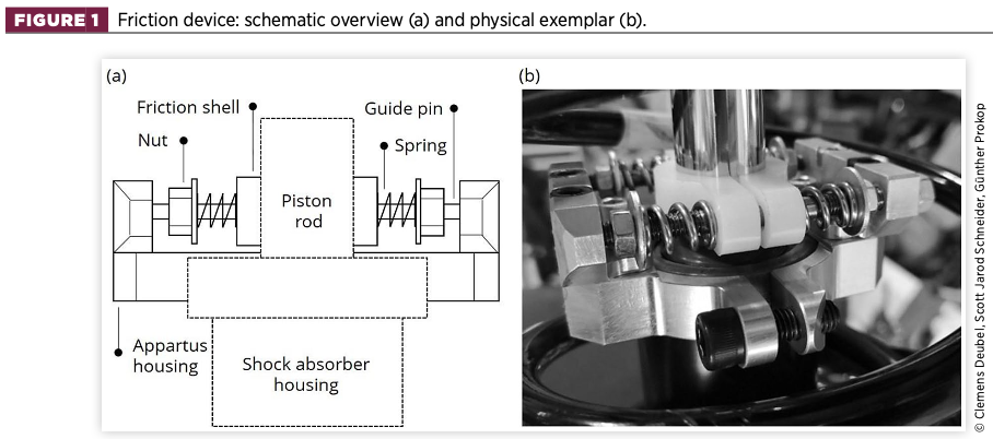
The frame or housing is manufactured in two pieces and holds two guide pins on which two friction shells made of polyamide PA6 are mounted. This material is characterised by a high coefficient of friction and a sufficient wear resistance. An additional friction force is thus exerted by the shells, which are pressed against the piston rod by a total of four springs with a relatively high spring rate (38.8N/mm nominal stiffness). By adjusting the compression of the springs, the spring forces and thus the total friction force is varied.
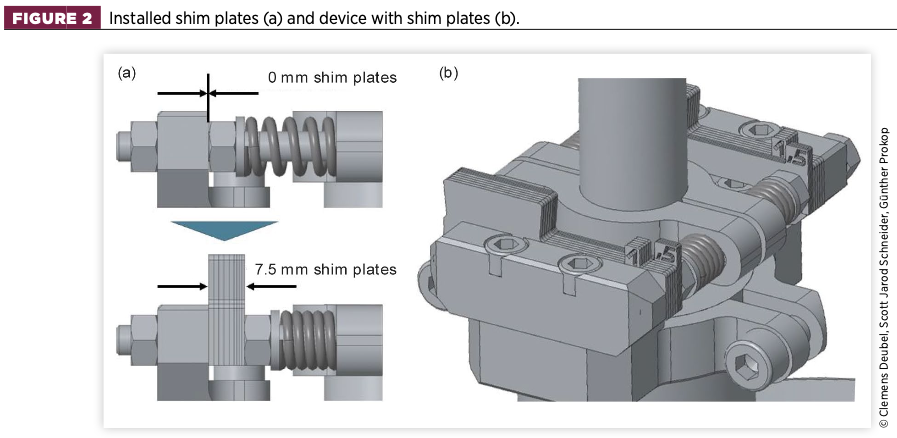
In order to achieve the desired friction force with a high degree of reproducibility, a specific adjustment routine is required. This is achieved by the use of so-called shim plates, as shown in Figure 2. The shim plates are installed between the device housing and the nuts, and provide a definite compression of the springs.
The total thickness of the shim plates can be up to 7.5mm, providing up to 150N of additional friction. The minimum increment is 0.5mm. In the nominal condition (no additional friction), a metal spacer was used to keep the friction shells separated from the piston rod.
The spring-loaded design provides the advantage of having a uniform compression. Since the guide pins of the unit are aligned in the longitudinal direction of the vehicle (as shown in Figure 1), a bending of the piston rod in this direction is easily possible, resulting in slightly more compression on one friction shell, and slightly less compression on the other.
Because of the linear spring characteristic and the linear dependency of the applied friction on the spring compression (see next section), the total friction force applied by the device remains constant. The friction shells are provided with long holes in the lateral direction of the vehicle, and thus bending in this direction is likewise possible by moving the shells slightly in a lateral direction. In the vertical direction, these holes do not allow any relative motion. This design allows the damper to stick if the friction force is sufficient.
Since the device is mounted close to the damper rod bearing, excessive rod deflection is not expected. Tests on the strut system, in which a side force was applied to the TM, representing the real side load on the strut [20], showed no noticeable differences in terms of applied additional friction to the case without side force.
2.2. Calibration
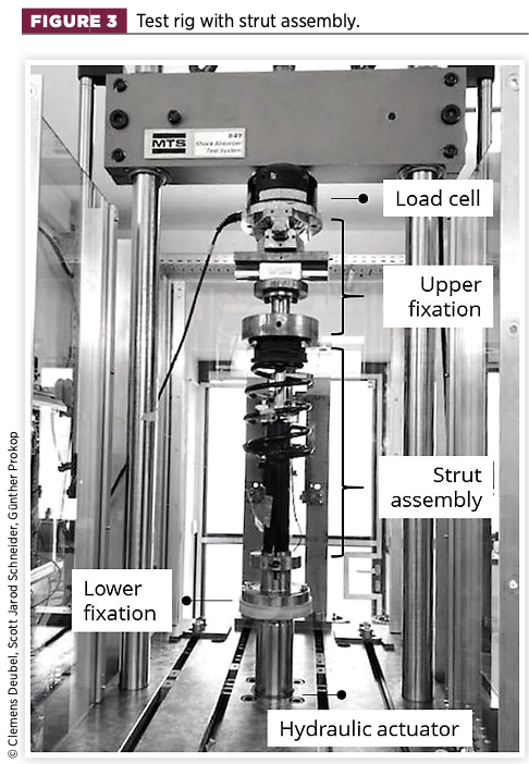
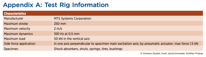
Calibration was performed to evaluate the actual application of additional friction as a function of spring compression. The tests were carried out on a hydropulser test rig, as depicted in Figure 3. In order to ensure its proper operation, the device was tested on the real components, which means that it is installed on the strut. More information on the test rig and test layout can be found in a previous study [9] and in Appendix A below.
The tests were divided into a quasi-static and a dynamic sequence, carried out for two devices and their associated strut assemblies (named D3 and D4) as used in the later driving tests, i.e., one for the front left wheel and front right wheel, respectively.
Quasi-static tests were performed at 3mm amplitude and 1mm/s velocity. One measurement consisted of 10 cycles (periods), of which the friction force was calculated from the displacement-force hysteresis as a mean value from the second to the last period. The quasi-static friction force, as termed in this study, is thus represented by half the hysteresis height at zero relative displacement.
The strut was preloaded to a state of 118mm free piston-rod length, which constitutes the defined reference deflection (approx. 3,500N vertical load). Each measurement, i.e., setting of shim plates (spring compression), was repeated two times consecutively in order to achieve a steady state.
The second repetition was used to compile the curves of Figure 4, which illustrates the linear relationship between applied spring compression and friction, due to the linear relationship between normal force and friction (which is, in fact, a simplification, but is approximately true here as well).
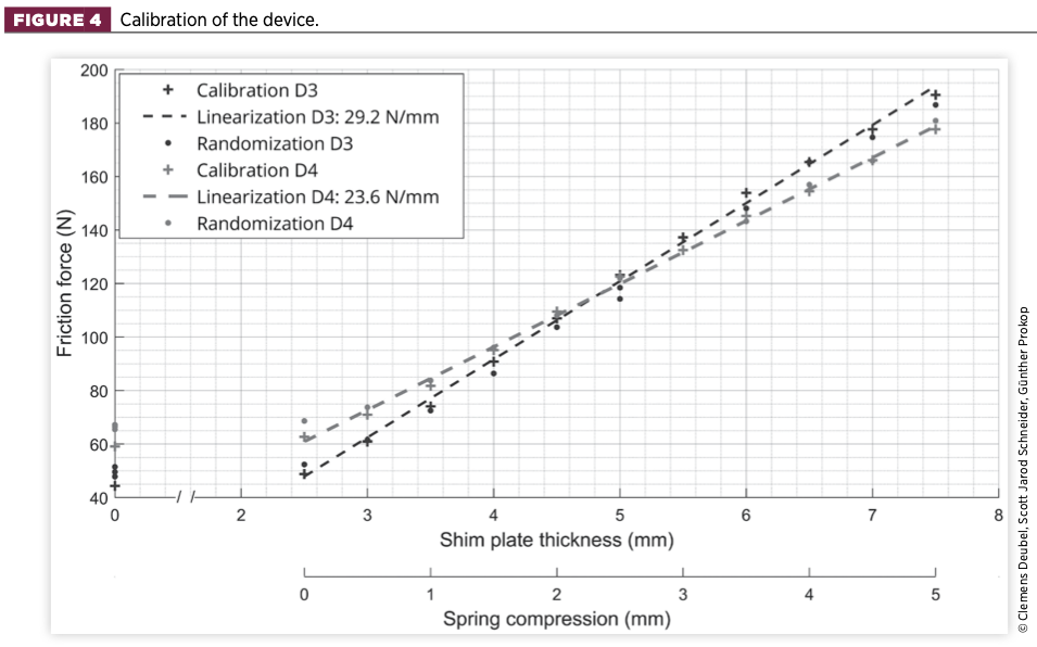
The configurations of 0 and 2.5mm shim-plate thickness differ only insignificantly. This is because 2.5mm marks the point at which the friction shells begin to press against the piston rod, thus creating additional friction. For simplicity, this point is referred to as ‘0 mm spring compression’.
It is obvious that the friction rate is not equal for both devices. However, the basis friction values of the associated dampers are not equal either. Thus, in combination, two closely located curves are obtained.
Some additional randomised tests, i.e., without a monotonous increase or decrease of spring compression, were performed for further analysis. While these tests show a greater deviation from the linearisation, there is still a clear distinction of the operating points in terms of the resulting friction force present.
In addition to the static calibration, dynamic experiments were performed to further ensure the proper functioning of the device in real driving due to the higher dynamics. In order to establish a definite link between the applied friction and its effect on the vehicle’s vertical dynamics, the applied friction must be clearly determined, i.e., must be equal to the static (reference) tests from which it was identified.
For the dynamic test sequence, a real, medium-dynamic damper displacement signal with velocities up to 230mm/s was used. It was recorded from real driving tests and is visualised in Figure 5. The tests were performed exemplarily for damper D3 and for the cases of 0/0.5/2.5/4.5mm spring compression. Each configuration was repeated twice. For visualisation purposes, the two repetitions of each test were averaged and filtered.
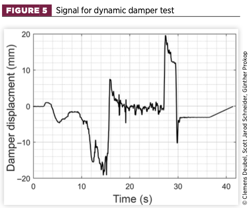
Figure 6(a) provides a time domain section for the 0.5 and 4.5mm configurations. The forces are offset so that there is zero difference in the rebound direction of motion. Consequently, as soon as the direction reverses, the full hysteresis height (i.e., two times the friction, as previously defined) is applied. Once there is full sliding, e.g., 3.5-5.5s, a nearly constant force difference of approximately 230N takes place. This value agrees accurately with the static tests for these two configurations.
Figure 6(b) therefore shows the calculated force differences for certain spring compressions (0.5/2.5/4.5mm) relative to the nominal condition (0mm) over a wider time range. Assuming identical damping behaviour, the hydraulic damping force is eliminated, leaving only the operating friction force. The dashed lines represent the friction force potential provided by the respective configuration during the static randomisation sequence, multiplied by two because of the specific offset convention chosen.
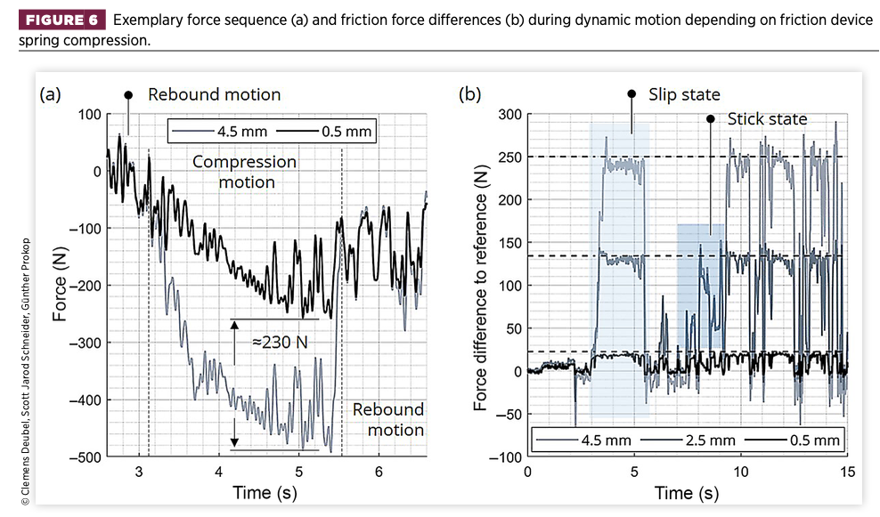
Regions, where the full available friction potential is displayed (dashed lines), represent gross sliding or the slip state. Again, the forces agree with the static tests with minor deviations. Sections of lower forces (than the dashed lines), e.g., 7-9s, represent the stick state. Here, the friction potential is not fully applied, because the externally excited motion does not require the full friction force to be present in order to keep the damper stuck.
This can be seen by the fact that the curves of the two configurations show similar forces despite the different friction potential. Again, note that sticking is made possible by the strut assembly and the resulting deflection of the TM.
Because of the strut assembly, the friction of the damper and the TM itself are present at the same time and are subject to deviation. In consequence, as the dynamic calibration shows a high agreement with the static tests during sliding, it is concluded that there is no noteworthy velocity-dependent friction evolution of the additional friction of the device.
The presented results of the dynamic segment thus demonstrate the correct functioning of the device to apply a definite set of friction forces, even during a realistic damper movement, where sticking of the damper is potentially enabled.
Section 3: Pre-investigation on the friction effect by simulation
Before presenting the physical experiments, a simulative approach was introduced with the aim of improving the understanding of the driving test results as presented in Section 4. Since the objective was thus not to achieve perfect agreement with the physical experiments, certain simplifications were made, as described below.
Regardless of the abstractions compared to a real vehicle, the friction effect on the vibration level and the eigenfrequency bands of the sprung and unsprung masses (hereafter referred to as body and wheel) can be studied qualitatively.
3.1. Simulation setup
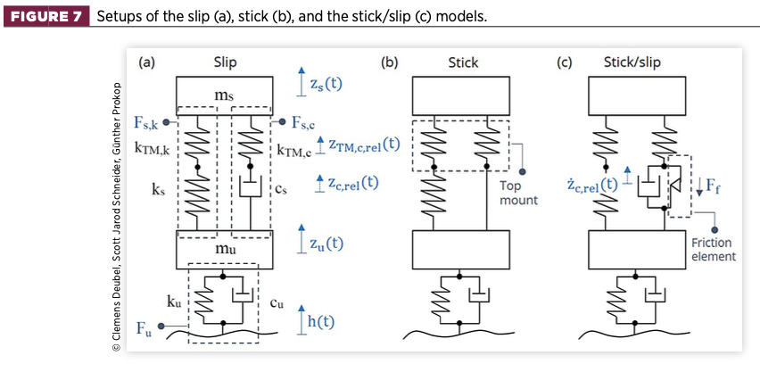
In reality, both the stick and slip of the damper occur and alternate, depending on the road profile and the amount of friction. Therefore, a quarter-car model of different topologies, as displayed in Figure 7, was designed in order to study the stick and slip phenomena in detail.
A TM model is required to realistically enable sticking of the damper. In the MacPherson suspension, the TM bushing consists of two paths, each represented by a spring element at the suspension spring and damper paths, respectively.
The following investigations were performed with reference to Figure 7:
- Investigation on the damper stick and slip states separately, which are analysed in comparison, by using the corresponding slip (a) and stick (b) modelling topologies. This approach was formerly presented in Geluk’s work [19].
In the case of constant stick [Figure 7(b)], the damper (damping element) does not allow any relative displacement, resulting in a strong stiffening of the suspension due to the two parallel spring sets. Conversely, for constant slip [Figure 7(a)], the relative motion of the damper basically decreases the stiffness of the damper path instead. - Investigation on the combined stick and slip states of the damper, which can occur to varying degrees depending on the amount of friction, the remaining system properties, and the road profile.
This was achieved by applying the topology of the so-called ‘stick/slip’ quarter-car model of Figure 7(c). Thus, a friction element exerting the force Ff was added, making the system non-linear.
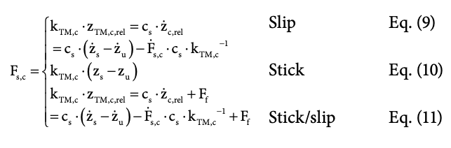
The friction force is represented by a Dahl model [21]:
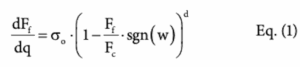
where Fc is the Coulomb friction (maximum friction potential), Ff is the actual friction force provided by the friction model, σo is the contact stiffness in the pre-sliding regime, w the relative velocity, d the form parameter affecting the hysteresis shape, and q describes the position in the first-order differential equation.
To the best of the authors’ knowledge, the Dahl model cannot be attributed to all frictional properties of automotive dampers. Nevertheless, it is well suited to the requirements of this study because of its ability to represent stiction and sliding friction. Stiction is defined here as the model’s ability to provide the force Ff necessary to keep the body macroscopically at rest in the presence of an external force by applying pre-sliding (as long as the friction potential is not exceeded).
Conversely, static friction models, such as the Coulomb model, act as a damper and are not capable of enabling stick, since the model force presupposes a macroscopic (gross) sliding motion. A second property applies during gross sliding, where the friction converges to the Coulomb friction force Fc. This independence of the velocity simplifies the analysis.
The universal equations of motion for determining the absolute accelerations Zs, Zu of the sprung and unsprung masses (ms, mu) are:
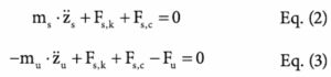
The force of the unsprung mass Fu is expressed by a Kelvin-Voigt element, and the force of the sprung spring path Fs, k constitutes a series of springs with a replacement stiffness krep. The road input is defined by h(t).
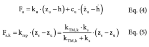
The force of the sprung damper path Fs, c is variable, depending on the modelling approach. While there is only a single spring element in the stick model, there is a Maxwell element in the slip model.
For the Maxwell element, the force of the spring and damper element are equal. The relative displacement zrel between the sprung and unsprung masses is the sum of the relative (i.e., effective) displacements of the spring element zTM, c, rel and the damper element zc, rel [22]:
![]()
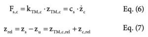
In the stick/slip case (non-linear topology), in which both stick and slip alternate depending on the system’s state, a Bingham-Hooke element [22] represents the damper path. Here, the force of the friction element Ff is a function of the relative damper velocity zc, rel and is parameterised by the Dahl model parameters (cf. Table 1). The sprung damper path force Fs, c is then defined as:
When solving Equation 11 in MATLAB/Simulink (Runge-Kutta ode4 solver, fixed step), it is beneficial to determine the relative displacement of the damper TM element. This is because a displacement of the TM element takes place both in the damper’s stick and slip case. Thus, the force of the Bingham-Hooke element can be solved at any time and no case discrimination is required.
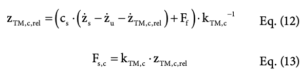
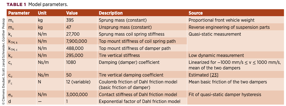
Table 1 provides the linear model parameters, including their definition as used for the subsequent study. Except for the friction model, the quarter-car parameters are chosen to be linear to simplify the analysis for the benefit of observing the non-linear friction effect more easily and singularly. In this way, other non-linear effects, for instance those caused by typically very non-linear dampers, can be avoided.
3.2. Analysis of vertical model dynamics
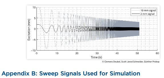
A sweep signal in the range of 0.1-30Hz is used. Two amplitude versions are used and the amplitude decreases logarithmically. The initial values are 2mm (‘low amplitude’) or 10mm (‘high amplitude’) and the signals are provided in Appendix B. The amplitude decrease is used to mimic the signal content of real roads, which generally decreases with increasing frequency. Refer to the ISO8608 standard [24] for further information.
All computed PSDs are smoothed with a moving-average filter in order to reduce variance and obtain a clearer visibility (‘noise reduction’).
Figure 8 depicts the results of the stick and slip models (without friction) for the sweep signal. Since the models used are linear, they yield the same results for the low and high amplitude signals. For qualitative comparison, the curves are normalised to their respective maximums.
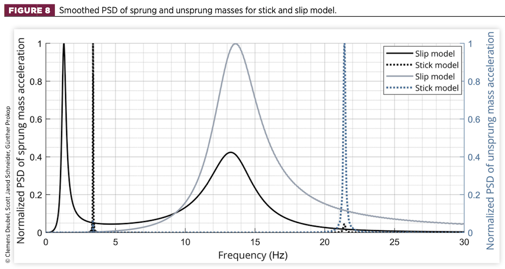
For the slip model, the eigenfrequencies of the sprung and unsprung masses are visible at 1.3Hz and 13.3Hz. In the stick model, the resulting vertical stiffness of the suspension shifts from approximately 28 to 516N/mm, owing to the parallel setting of the coil spring and TM stiffness. This results in an increased eigenfrequency of the sprung mass of 3.4Hz within a narrow frequency band, owing to the absence of suspension damping. Here, the sprung mass vibrates together with the unsprung masses (i.e., highly coupled by the stiff TM) on the tyre spring.
This results in a relatively strong peak in the unsprung mass PSD, which is masked by the even much higher resonance of the unsprung masses at their own eigenfrequency at 21.4Hz, which is similarly sharp in appearance. Therefore, sticking is characterised by a shift of the two eigenfrequencies, as a consequence of the higher effective suspension stiffness, and potentially by an increased wheel vibration at the sprung mass eigenfrequency (see also presentation in Section 4).
Next, a friction force variation of the non-linear system (stick/slip model) is presented for the high amplitude (10mm). The friction was varied from 12 to 120N, which is a realistic range according to the capability of the presented friction device.
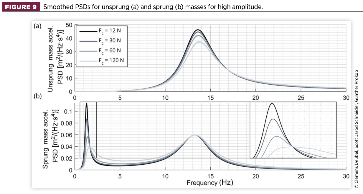
The curves in Figure 9 show a high similarity to the slip model, with smooth-appearing resonance peaks of the sprung and unsprung masses at similar frequencies. In contrast to the stick model, there are no distinct peaks at higher frequencies. This indicates the absence of significant and prolonged sticking of the suspension.
With regard to the detail of Figure 9(b), the effect of friction is thus primarily that of a damping element, effectively reducing the vehicle body vibration in the range of its eigenfrequency. At the same time, the eigenfrequency is slightly increased, due to the increase of equivalent suspension stiffness.
As reported in the literature [14, 17], there is an increased vibration level in the subsequent transition region as a consequence of high friction or damping, resulting in less relative motion of body and wheel. This is also the case in this study. Even if no stick occurs, the level of coupling between the sprung and unsprung masses increases. Thus, even in the range of the wheel eigenfrequency, the body’s vibration level is slightly increased because the excessive wheel motion is more strongly transmitted to the body.
The equivalent damping effect is also evident with respect to wheel acceleration, as the vibration is reduced at the wheel eigenfrequency – see Figure 9(a). The effect below and above this frequency is rather insignificant.
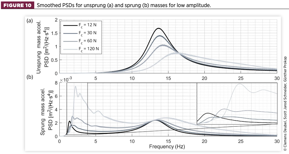
If the initial sweep amplitude is reduced from 10mm to 2mm, the body acceleration PSD is altered with reference to Figure 10:
- Depending on the amount of friction, two resonance peaks appear in the frequency range up to 5Hz. The first peak, referred to in this article as the ‘slip eigenfrequency’, begins again at 1.3Hz and rises successively as the friction increases. The second peak, referred to as the ‘stick eigenfrequency’ according to the stick model, is close to the former mentioned 3.4Hz.
Thus, it is clear that both the stick and slip states occur during the simulation, resulting in two distinct types of motion of the body (i.e., once against the unsprung masses, once highly coupled with the unsprung masses primarily against the tyre spring element). - The intensity of the stick resonance increases as the friction increases. With respect to time, stick occurs mainly at the beginning of the sweep signal during the period of relatively low excitation frequency. Here, the body oscillates at a higher frequency, owing to the nonlinearity of the system. At higher excitation frequencies, the stick phases are only partially present and gradually decrease.
This is the reason why the stick peaks in Figure 10(b) are rather weak and less distinct, since excessive slip occurs at the same excitation frequency. It can be seen that by further increasing the friction or decreasing the signal amplitude, the stick eigenfrequency becomes more and more pronounced or even dominant compared to the slip eigenfrequency (Figure 11(b)).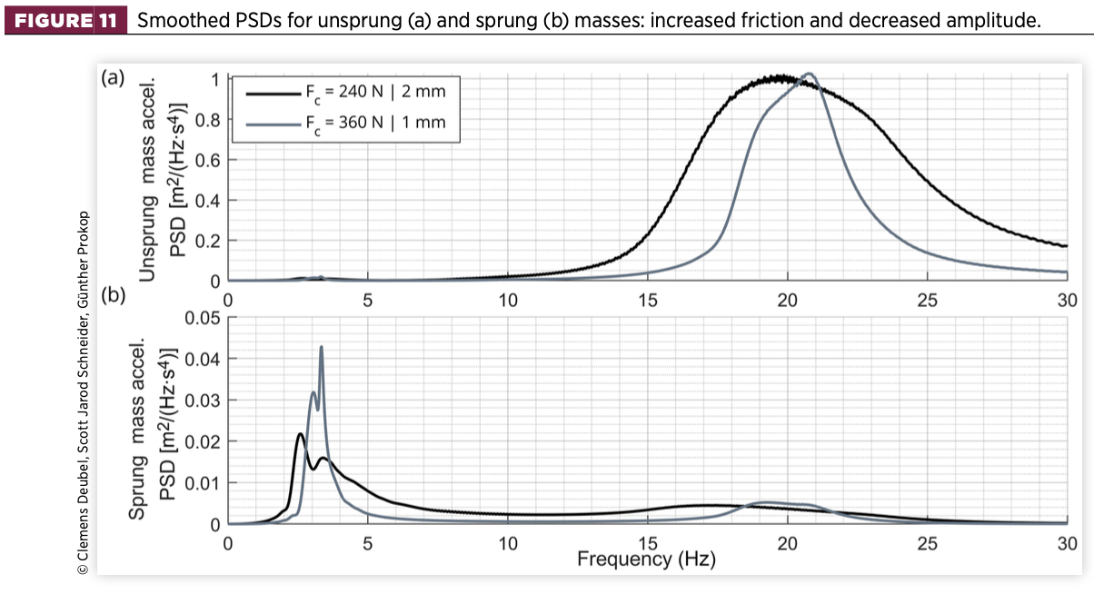
- For the high amplitude, the magnitude in the region of the slip eigenfrequency decreases with increasing friction. For the low amplitude, although it also decreases initially (Fc = 12 → 30 N), it increases again for the following friction steps (Fc = 60 ∣ 120 N). This is because, as long as the stick phases of the damper are limited, the character of the friction is rather damping-like, as shown in Figure 9(b), and the body acceleration decreases.
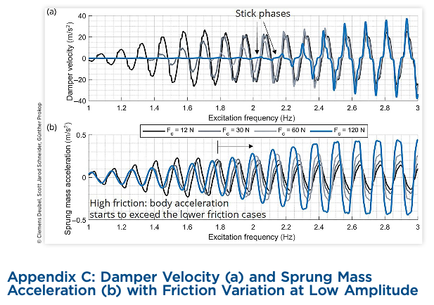
- However, in the present combination of low excitation amplitude and high friction, the slip-eigenfrequency range and the excitation frequency range, in which a high amount of sticking occurs, fall largely together. Thus, in this case, the slip-resonance peak increases owing to the limited relative motion or velocity of the damper. Consequently, the absolute body motion and its acceleration increase. This can be observed in Appendix C (time domain), where the time (x) axis is replaced by the excitation frequency of the sweep signal being present with respect to time.
- The body acceleration in the range between the body eigenfrequency and the wheel eigenfrequency, as well as above the wheel eigenfrequency, is more affected by higher friction forces at lower amplitudes. This is because the relevance of the friction is higher at lower amplitudes, resulting in a relatively higher body acceleration.
- Regarding the unsprung mass PSD, the decrease of acceleration at the wheel eigenfrequency is more pronounced at the lower amplitude, resulting in a greater increase of acceleration in the region beyond. In case of high friction, the wheel eigenfrequency shifts to a higher frequency. Again, at even higher friction [Figure 11(a)], the wheel-slip eigenfrequency is almost completely reduced and the wheel-stick eigenfrequency becomes dominant.
- For the wheel PSD, however, no peak can be observed in the range of the body-stick eigenfrequency. Only when the friction is further increased (Figure 11(a)), the peak becomes slightly visible.
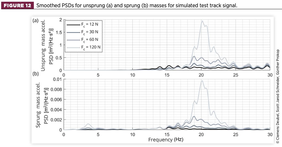
Finally, a road profile of the test track (class A according to ISO8608 classification [24]) driven in the driving tests was also used in the simulation at 50km/h, and the results are depicted in Figure 12. The shift of the wheel eigenfrequency to about 20Hz can be seen. In the case of stick, the wheel vibration is transmitted to the body without damping, resulting in a high peak for the sprung mass in the same frequency range.
The presented data indicates that stick of the body mode and of the wheel mode are distinct phenomena that may or may not occur together, depending on the excitation level of the road in the respective frequency bands and the system parameters – especially the friction characteristics.
Investigation on the friction effect by driving tests
4.1. Overview
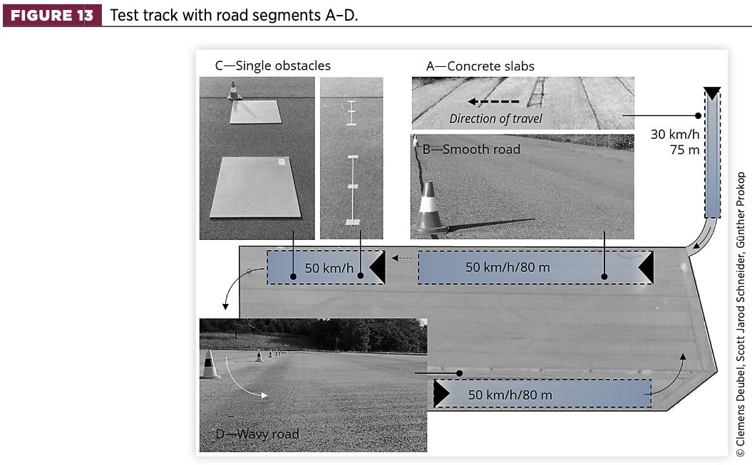
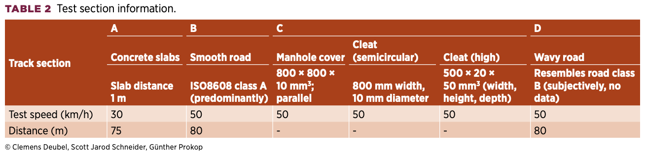
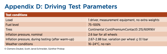
The friction device presented in Section 2 was mounted on the front suspension of a Volkswagen Passat B8, which was driven on several road sections, as shown in Figure 13. For additional information, their characteristics are listed in Table 2. Further test parameters are listed in Appendix D.
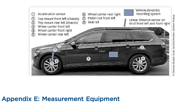
The test vehicle was equipped with several sensors, of which the triaxial piezoelectric accelerometers of the front left wheel carrier, piston rod, TM, and seat rail were primarily used for subsequent analysis, supplemented by signals from a vehicle dynamics recording system (e.g., centre of gravity acceleration). A complete overview of the measurement equipment is given in Appendix E.
The tests were performed in a randomised manner for 0|0.5|1.5|2.5|3.5|4.5 mm spring compression of the friction device, representing 0|13|40|66|92|119 N of additional friction (Ff, add) averaged for both wheel sides. Each configuration was consecutively repeated at least five times.
4.2. Investigation on the damper’s stick state
The stick or slip state of the damper determines the proper functioning of the suspension and thus the transmission of road disturbances to the passenger. The stick state can be analysed in two ways: (i) directly, by analysing the time history of the relative displacement between damper housing and piston rod; and (ii) indirectly, by analysing the vertical wheel acceleration in the frequency domain. The first method provides the advantage of identifying distinct time frames of stick, but is limited by the quality and resolution of the displacement signal.
For (ii), time assignment with satisfactory time resolution is impossible, but a more general assessment whether stick is likely to occur over the course of the test or not is possible (see Section 3).
Method (i) initially utilised the displacement sensor located between the damper housing and the TM on the chassis side. However, to record the relative motion between the housing and the piston rod, it is necessary to use a set of two acceleration sensors: one placed on the top of the piston rod and the other on the chassis side of the TM, since the TM bushing is elastic.
By integrating and subsequently high-pass filtering (with a 0.75Hz cut-off frequency to avoid signal drift), the displacement signals were calculated. The difference between the two signals represents the elastic deformation of the TM, which was then applied to adjust the displacement signal of the damper. When the time history of the signals was examined, individual stick sequences could not be identified due to signal noise.
Therefore, the frequency domain method was utilised to present the results related to segments B and D. While segment B represents a road of ISO8608 class A (‘smooth road’), segment D is characterised by periodic low-amplitude waves (‘wavy road’), which also result in roll vibrations of the vehicle. Subjectively, segment D resembles an average country road of class B.
To calculate a representative PSD, the PSDs of single repetitions per configuration are averaged to reduce variance, in analogy to Bartlett’s method of averaged periodograms [25].
The wheel and body PSDs are calculated from the front left wheel vertical acceleration and of the centre of gravity vertical acceleration provided by the vehicle dynamics recording system. Alternatively, qualitatively similar results for the body can be obtained from the seat rail acceleration.
4.2.1. Wavy road (Segment D)
The smoothed PSDs are presented in Figure 14 and reveal the presence of four modes (two each for the wheel and body). Regarding the wheel-slip resonance (3) at 12-13Hz, in agreement with the simulation, the increasing friction decreases the energy in this frequency range, thus decreasing the slip eigenfrequency. Conversely, the wheel-stick resonance (4) at about 19-20Hz shows increased prominence.
Since the area of the PSD in a certain frequency band equals the squared root-mean-square (RMS) value of the same band-pass filtered signal in the time domain, a higher RMS value indicates either a higher magnitude or a longer portion of that vibration occurring relative to the total signal length. In the moment of stick, there is no intensification possible and thus the same friction force is present for a certain combination of magnitude and frequency. Thus, a higher peak in the spectrum indicates prolonged stick in relation to the overall duration of the signal.
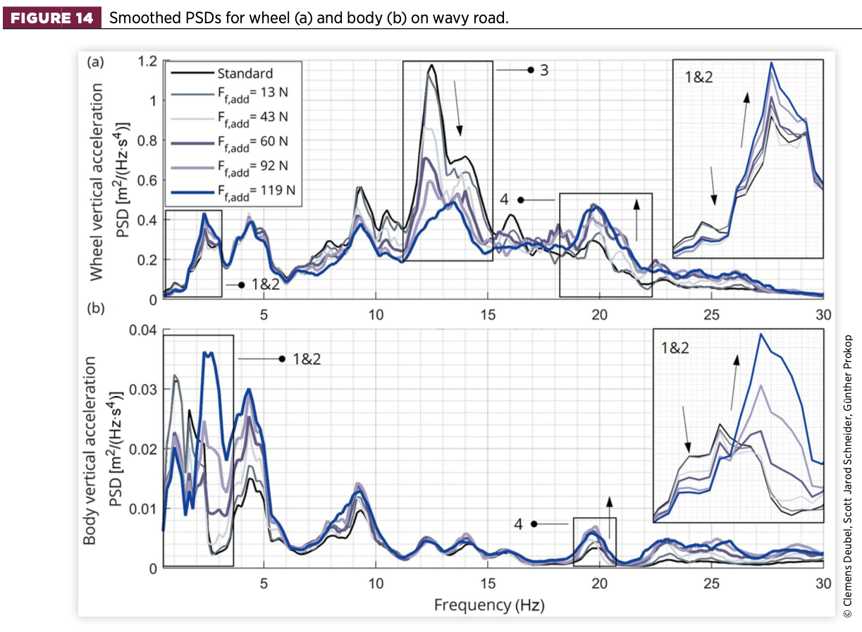
However, for the vehicle passenger, the resulting body acceleration is relatively insignificant in this case because there is considerably more energy within the body harmonics range (<5Hz). On the one hand, the decrease of the body-slip resonance (1) is evident, indicating that the excitation power is sufficient in that frequency range to cause slip. Thus, the additional amount of friction has a damping effect.
Similarly, the body also experiences noticeable periods of sticking, resulting in higher frequent stick vibrations (2). Increasing the amount of additional friction leads to an increase in the power density of the stick vibration, indicating longer periods of stick regarding the body resonance. Coupled with the peak at 4.5Hz, which is associated with the measured vehicle roll acceleration, the vertical ride comfort deteriorates significantly.
Since the body PSD peaks in the body resonance range are relatively high, they are also reflected in the wheel PSD. In the stick mode, the coupled motion against the tyre results in higher tyre deflections, which is potentially detrimental to the vertical wheel-load deviation and thus driving safety.
4.2.2. Smooth road (Segment B)
The results for the smooth road are presented in Figure 15. The wheel PSD indicates that most of the power is present in the range of 20-30Hz. The wheel-slip mode (3) is not clearly observed, nor is the body-slip mode (1). However, the body-stick mode (2) with its corresponding increase by increasing friction is well defined. This implies sticking over a wide range of the measurement, creating the higher added friction. While there is some vibration at about 20Hz present (the designated stick eigenfrequency so far), there exists an even higher peak at around 24Hz.
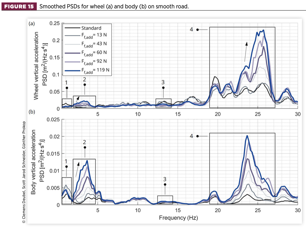
This scenario involves two causal factors: (1) an increased tyre stiffness and/or (2) an increased TM stiffness. As a result of the small road excitation amplitude, the tyre deflection is likewise reduced. However, a large increase of the tyre stiffness would be required (more than double) to increase the wheel eigenfrequency to the current level, which is unrealistic.
Therefore, the TM was re-analysed and experiments were performed at low amplitude (0.2mm) resembling the TM amplitude range calculated from the driving tests, and at low dynamics (1 Hz). The results show a stiffness increases for the damper path from 488N/mm (high amplitude) to 707N/mm. Applying this to the model, the wheel PSD shows excessive peaks between 22.5 and 25Hz, which is very similar to the driving test results.
In reality, a combination of both an increased tyre stiffness and an increased TM mount stiffness is likely to occur, but the TM stiffness is assumed to be the predominant parameter for further increasing the wheel- stick eigenfrequency.
For the vertical body vibration, the wheel-stick mode (4) is now more present compared to the wavy road and generates the highest power density next to the body-stick mode (2) at about 3-4Hz. From the height of the curves, it is evident that stick becomes the dominant body mode as the amount of additional friction increases.
4.2.3. Energy transfer along the vertical path
The amount of energy transferred from the wheel to the chassis is closely related to the stick and slip states of the damper. Therefore, the transfer path starting from the wheel via the piston rod to the TM (chassis side) is investigated by analysing the respective vertical accelerations from Figure 16.
On the smooth road, a substantial amount of energy is transferred from the wheel to the piston rod over the entire frequency band, again characterising excessive stick. The frequency-dependent operation of the TM can be well observed, as the energy is almost completely transmitted to the chassis in the range of the body eigenfrequency, while it is largely dissipated in the range of the wheel eigenfrequency and beyond. The TM acts damper-like, when the wheel and the damper vibrate together against the chassis in the wheel-stick mode range.
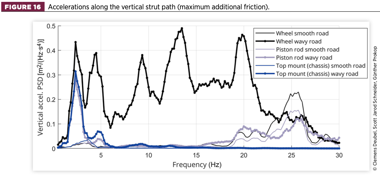
Regarding the wavy road, most of the energy is transferred from the wheel to the piston rod in the body-stick mode. At higher frequencies, the acceleration at the piston rod is low, which implies that the damper function is widely active. Even in the wheel-stick mode at 20Hz, there is a noticeable gap, but the piston rod still retains power.
This signifies once more that both stick and slip occur at this frequency, depending on the intensity of the road excitation. Again, in the higher frequency bands the energy is mainly absorbed by the TM, resulting in a very flat PSD line of the chassis.
4.3. Objective ride comfort values
Friction affects the vertical body acceleration over a wide frequency range (see Figures 9, 10, 14, 15). This occurs regardless of whether it leads to suspension stick and can therefore be considered detrimental to ride comfort. Only in case of insufficient damping does friction contribute to limiting the vertical body acceleration. In this context, the term ‘discomfort’ is introduced and used to define the level of adverse vibration present in a specific vehicle-driver interface for the passenger to be experienced, such as the seat, foot space, and steering wheel.
Since subjective data of experienced test drivers are not available for the present study, no classical subjective–objective correlation was performed. Instead, an objective–objective relationship (suspension setting to a certain ride comfort value) was determined. This is meaningful as, unlike in most studies, the suspension setting variation (that is the modified damper friction) is known exactly. Hence, this relationship is utilised to describe the impact on ride comfort in a general manner, excluding subjective evaluation.
Thus, the friction effect is expressed in terms of scalar ride-comfort values. There are several approaches to express ride comfort in integral or rather phenomenon-specific terms [26]. Some studies have pointed out, in accordance with the ISO2631-1 standard [27], that the vertical seat and foot (space) acceleration, plus the longitudinal seat vibration contribute most to the overall ride comfort [28, 29, 30].
The approach involves utilising integral methods (e.g., RMS acceleration) to the test track sections A, B, and D (consecutive concrete slabs, smooth road, wavy road), as was performed in several studies [28, 29, 30, 31, 32]. For the single obstacles (section C), the initial moment of passing the obstacle is analysed, which can be attributed to the phenomenon of ‘impact hardness’ [33, 34].
According to Figure 17, an RMS value is calculated from inserting vertical acceleration to the second (i.e., negative) peak, while the initial positive and negative peaks are used to calculate the peak-to-peak (P2P) value [33, 34].
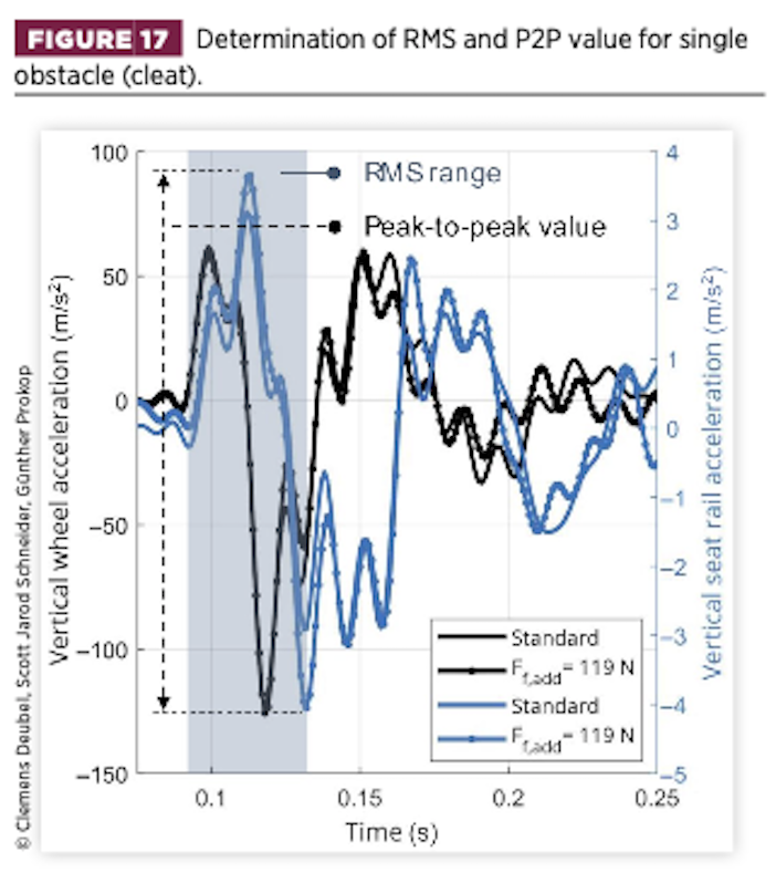
For both approaches, the seat-rail vertical acceleration (SRv) is used. For section C, the investigation is extended to the seat rail longitudinal acceleration (SRl). The seat rail is beneficial in this context because it measures the acceleration close to the driver, while excluding the suspension-like seat characteristics. For instance, a well-designed seat structure can mitigate some of the effects of a poorly designed suspension system by reducing acceleration for the passenger.
However, the main objective of this study is the transfer path from the road to the chassis. Additionally, the driver constitutes another multi-mass system that affects the seat acceleration through its own motion, which varies over the duration of the tests.
The calculation is presented two-fold, once unweighted (uw) and once weighted (w) according to the ISO2631-1 standard, while the seat-rail acceleration used represents the floor acceleration.
Furthermore, for the consecutive concrete slabs, smooth road, and wavy road (sections A, B, D) the unweighted body pitch RMS acceleration is determined, as the vertical and pitch dynamics are interrelated. For the wavy road, the unweighted body-roll acceleration RMS is calculated because of the strongly differing road irregularities of the left and right wheel sides.
Every objective value is characterised by the Pearson correlation coefficient R and the inclination S of the regression. R indicates the linearity of the paired objective–objective data {(xi, yi),..,(xn, yn)}.
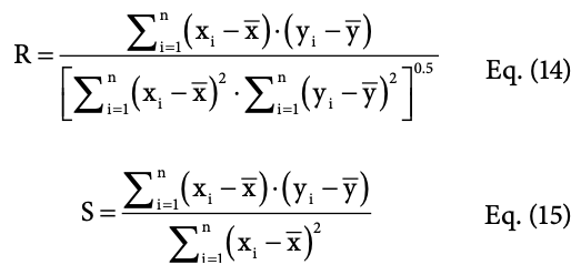
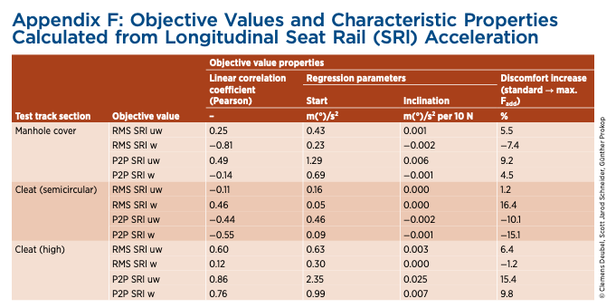
Table 3 lists the calculated objective values for vertical, roll, and pitch acceleration along with their relevant characteristics. The data of the longitudinal objective values are not listed, because only a minor correlation is observed, indicating insignificant influence of the friction variation (see Appendix F).
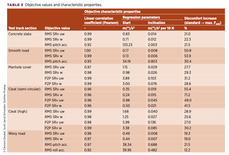
Conversely, all the listed values demonstrate a high linear correlation toward increased friction. The addition of maximum friction increases vertical discomfort by 19-71% regarding vertical acceleration. As expected, the effect diminishes the more severe the road excitation.
For severe singular excitations (concrete slabs, manhole cover, high cleat), it varies from 21% to 31%. For the light excitations (smooth road, semi-circular cleat) the variation is 41-71%. The semicircular cleat is particularly noteworthy as it resembles the expansion joints commonly used for repaired road sections, and is therefore of high practical relevance.
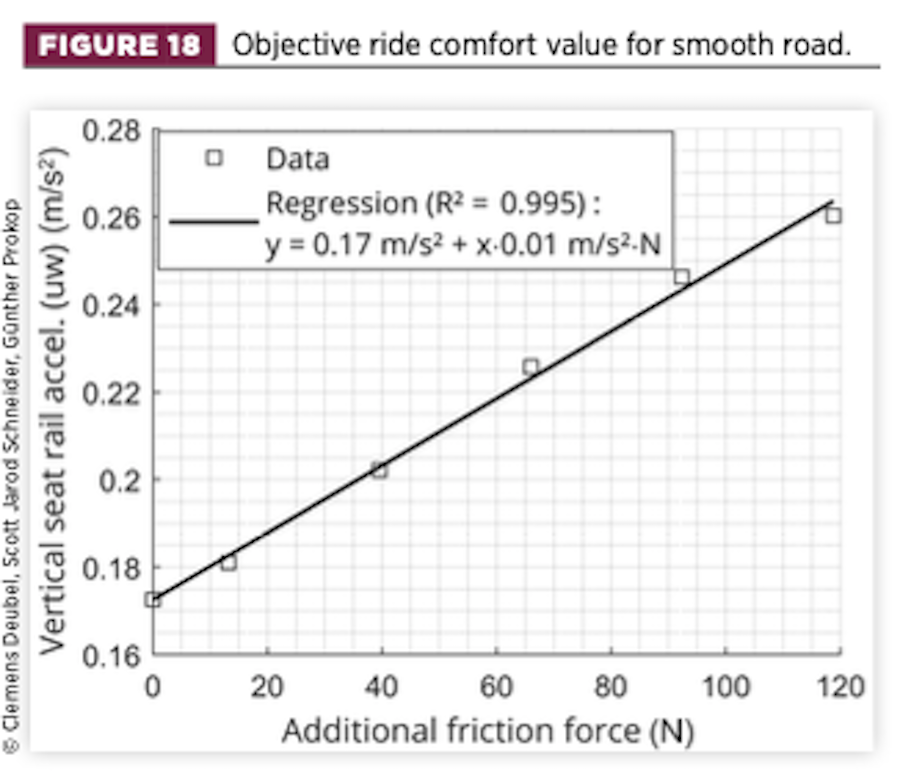
For the smooth road (Figure 18) the increase is also remarkable, which might be compared to a highway or a newly built urban road. Conversely, on the wavy road, the increase in vertical and roll discomfort is relatively moderate.
The interrelation of the friction effect and the road quality can thus be confirmed in an experimental setting. Even a slight decrease in road quality (from smooth to wavy) results in a rapid weakening of the friction effect.
Now, for most suspension layouts, the friction of the damper or shock absorber will not increase relevantly during driving. This is quite different for the strut-type (MacPherson) design of the test vehicle, as the damper friction is strongly affected by the tyre forces (and other boundary conditions). Particularly during cornering, high lateral tyre forces become operative, increasing the side force acting on the damper and its generated friction [9, 12].
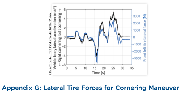
Even during medium cornering (cf. Appendix G), there are noticeable lateral forces that will lead to a similar increase of damper friction as that applied during this study. If these roads were to be driven during cornering (ignoring other suspension effects, like bushing stiffening effects, for this simplified example) a similar effect on the discomfort can be expected.
In reality, damper friction is highly variable and depends on the suspension’s kinematic and kinetic state, which encompasses particularly the wheel deflection and tyre forces, plus moments generated in the driving situation. Therefore, the presentation of constant friction at a variable level is the initial step in demonstrating the friction effect experimentally for the selected driving manoeuvres.
In general terms, the quantitative impact will also vary based on driving speed and for time-variable friction forces. Although a comprehensive and more precise analysis on this subject is outside the scope of this study, the presented outcomes demonstrate the fundamental significance of suspension friction and its effect on the vertical dynamics for different road profiles.
5. Conclusion
This study presents an experimental investigation on the effect of suspension friction on the vehicle vertical dynamics, with a focus on ride comfort.
The damper is an important component in MacPherson suspension systems with respect to the overall friction of the suspension. In order to enable experimental observations of the friction effect in a new way, this study introduces a device for modifying the friction of the damper, which applies additional friction.
By analysing the driving tests, certain eigenfrequencies of the wheel and vehicle body are identified, which can be attributed to the stick and slip states of the damper. The occurrence of these states depends on the level of additional friction. By implementing a quarter-car model simulation approach, the observed effects and eigenfrequencies can be replicated and therefore justified.
When the damper’s friction is high enough, a total of four eigenmodes occur, two for the vehicle body and two for the wheel, because of the effect of friction on increasing the effective suspension vertical stiffness. The wheel-stick mode and the body-stick mode are distinct phenomena that can occur together or separately, depending on the road’s frequency characteristics.
When analysing the vertical transfer path from the wheel to the body, it is found that the TM does not adequately absorb the coupled vibration of the damper and wheel assembly in the body-stick mode. As a result, high levels of vibration are transferred to the chassis, which the driver eventually perceives as increased discomfort.
In particular, the body-stick eigenmode is critical to ride comfort, as it constitutes a highly coupled motion with the wheel that renders the damper’s damping function inactive. This results in increased vertical vibration magnitudes of the body, which are shifted to higher frequencies. In the lower frequency band (<5Hz), they are perceived as more severe by human for a given vibration magnitude.
The friction effect on the vertical ride comfort is quantified by simple objective values, such as the RMS vertical seat rail acceleration. The comparison of various test track segments confirms the dependency of the increase in discomfort relative to the basic discomfort level on the road condition, being significantly higher on well-conditioned roads compared to poorly conditioned roads or severe single obstacles. The friction effect decreases rapidly as the road condition deteriorates.
It is justified to simplify the friction effect primarily on the vertical aspect of ride comfort for the tested vehicle and road segments, as the results emphasise only a minor significance regarding the longitudinal vibration of the chassis. Moreover, a coupling effect of the vertical and pitch dynamics is observed, showing higher pitch accelerations the higher the friction. The objective values demonstrate a significant linear relationship with friction variation, thereby establishing a direct link between suspension friction and (vertical) ride comfort.
It is recommended to conduct further tests on a wider range of vehicles to gain a more comprehensive understanding of the friction effect, as these conclusions are derived from a single vehicle with specific properties, such as sprung and unsprung masses, suspension stiffness and damping, and suspension layout and tire characteristics.
Nevertheless, the results are highly relevant to passenger vehicles equipped with MacPherson suspensions since the artificially applied damper friction forces observed in this study will potentially appear in real driving scenarios as a result of the side load. The results imply that the increased damper friction can significantly degrade ride comfort, particularly on high-quality roads and for specific manoeuvres causing high damper side-loads and thus internal friction, such as cornering or lane (acceleration or braking) manoeuvres.
In the future, a more comprehensive simulation study is needed to investigate the contribution of friction to undesired vertical vibration. It is recommended to study particularly the interaction of the various suspension components for relevant manoeuvres and to quantify the friction effect in more detail.
Especially for semi-active suspensions, which allow the damping forces to be reduced according to the driving situation, the friction force can become a major part of the total damper force. Therefore, the time-variable character of the friction potential must also be considered.
The findings encourage considering the existing, driving event-specific time-variable character of the damper’s friction force for control strategy and damper design. The elaboration and demonstration of this is hence the object of ongoing studies.
In addition, further research is required to examine the subjective perception of friction and the passenger’s acceptance in terms of appropriate ride comfort. This will aid in identifying design targets and thresholds in the context of the suspension development process.
Appendices
References
- Körner, F. and Mayer, R., “Analysis and Characterization of the Friction of Vehicle Body Vibration Dampers,” Automot. Engine Technol. 5 (2020): 79-90, doi: https://doi.org/10.1007/ s41104-020-00060-3.
- Hrovat, D., “Survey of Advanced Suspension Developments and Related Optimal Control Applications,” Automatica 33, no. 10 (1997): 1781-1817, doi: https://doi.org/10.1016/S0005- 1098(97)00101-5.
- Kumar, M.S. and Vijayarangan, S., “Analytical and Experimental Studies on Active Suspension System of Light Passenger Vehicle to Improve Ride Comfort,” Mechanika 65, no. 3 (2007): 34-41.
- Mántaras, D.A. and Luque, P., “Ride Comfort Performance of Different Active Suspension Systems,” Int. J. Veh. Des. 40, no. 1–3 (2006): 106-125, doi: https://doi.org/10.1504/ IJVD.2006.008456.
- Čorić, M., Deur, J., Kasać, J., Tseng, H.E. et al., “Optimisation of Active Suspension Control Inputs for Improved Vehicle Handling Performance,” Veh. Syst. Dyn. 54, no. 11 (2016): 1574-1600, doi: https://doi.org/10.1080/0042 3114.2016.1222075.
- León-Vargas, F., Garelli, F., and Zapateiro, M., “Limiting Vertical Acceleration for Ride Comfort in Active Suspension Systems,” Proc. Inst. Mech. Eng. Part I J. Syst. Control Eng. 232, no. 3 (2018): 223-232, doi: https://doi. org/10.1177/0959651817745469.
- Munawwarah, S. and Yakub, F., “Control Analysis of Vehicle Ride Comfort through Integrated Control Devices on the Quarter and Half Car Active Suspension Systems,” Proc. Inst. Mech. Eng. Part D J. Automob. Eng. 235, no. 5 (2021): 1256-1268, doi: https://doi.org/10.1177/0954407020968300.
- Komori, K., Fujimoto, G., Tsukamoto, T., and Endo, D., “Effect of Friction Reduction of Magneto-Rheological Semi-Active Damper on Ride Comfort and Vehicle Dynamics,” in 8th International Munich Chassis Symposium 2017, Munich, Germany, 309-329, 2017, doi: https://doi.org/10.1007/978-3-658-18459-9.
- Deubel, C., Schubert, B., and Prokop, G., “Quasi-Static Shock Absorber Friction at Low Velocity Reciprocating Sliding Conditions,” Proc. Inst. Mech. Eng. Part D J. Automob. Eng. (2023): 1-12, doi: https://doi.org/10.1177/09544070231201688.
- Lizarraga, J., Sala, J.A., and Biera, J., “Modelling of Friction Phenomena in Sliding Conditions in Suspension Shock Absorbers,” Veh. Syst. Dyn. 46, no. S1 (2008): 751-764, doi: https://doi.org/10.1080/00423110802037024.
- Xuwang, W., Chen, X., Xu, P., and Zhang, Y., “The Effect of Friction on Ride Comfort Simulation and Suspension Optimization,” SAE Technical Paper 2020-01-0765 (2020), doi: https://doi.org/10.4271/2020-01-0765.
- Deubel, C. and Prokop, G., “Friction of a MacPherson Suspension System at Various Load Cases,” J. Vib. Control 30, no. 1-2 (2024): 14-26, doi: https://doi.org/10.1177/10775463221140324.
- Yabuta, K., Hidaka, K., and Fukushima, N., “Effects of Suspension Friction on Vehicle Riding Comfort,” Veh. Syst. Dyn. 10, no. 2–3 (1981): 85-91, doi: https://doi. org/10.1080/00423118108968641.
- Manger, S., “Untersuchung des Schwingungsverhaltens von Kraftfahrzeugen bei kleinen Erregeramplituden unter besonderer Berucksichtigung der Coulombschen Reibung [Investigation on the Vibration Behaviour of Passenger Vehicles at Small Excitation Amplitudes under Particular Consideration of Coulomb Friction – in German],” PhD thesis, Universitat Karlsruhe (TH), 1995.
- Ilosvai, L. and Szücs, B., “Random Vehicle Vibrations as Effected by Dry Friction in Wheel Suspensions,” Veh. Syst. Dyn. 1, no. 3–4 (1972): 197-209, doi: https://doi. org/10.1080/00423117208968427.
- Koumura, S. and Shionoya, T., “Ride Comfort Analysis Considering Suspension Friction with Series Rigidity,” SAE Int. J. Passeng. Cars – Mech. Syst. 9, no. 1 (2016): 409-418, doi: https://doi.org/10.4271/2016-01-1679.
- Fujimoto, G., Komori, K., Tsukamoto, T., Sogawa, N. et al., “Influence of Shock Absorber Friction on Vehicle Ride- Comfort Studied by Numerical Simulation Using Classical Single Wheel Model,” SAE Technical Paper 2018-01-0692 (2018), doi: https://doi.org/10.4271/2018-01-0692.
- Wünsche, T., Muhr, K.-H., Biecker, K., and Schnaubelt, L., “Side Load Springs as a Solution to Minimize Adverse Side Loads Acting on the McPherson Strut,” SAE Technical Paper 940862 (1994), doi: https://doi.org/10.4271/940862.
- Geluk, C.T.T., “Vehicle Vibration Comfort: The Influence of Dry Friction in the Suspension,” Master’s thesis, Technische Universität Eindhoven, 2005.
- Deubel, C., Vincenz, H.J., and Prokop, G., “Shock Absorber Friction Testing on a MacPherson Suspension Considering Realistic Mounting Situation,” J. Vib. Control 29, no. 17-18 (2023): 4344-4356, doi: https://doi.org/10.1177/10775463221116488.
- Dahl, P.R., “A solid friction model,” Aerosp. Corp. El Segundo 18 (1968): 1-24.
- Nasdala, L., FEM-Formelsammlung Statik und Dynamik (Berlin, Germany: Vieweg+Teubner Verlag, 2012), doi: https:// doi.org/10.1007/978-3-8348-2260-4
- Rostami, H.T., Najafabadi, M.F., and Ganji, D.D., “Investigation of Tire Stiffness and Damping Coefficients Effects on Automobile Suspension System,” Proc. Inst. Mech. Eng. Part D J. Automob. Eng. 237, no. 14 (2023): 3313-3325, doi: https://doi.org/10.1177/09544070231151860.
- ISO, “Mechanical Vibration–Road Surface Profiles – Reporting of Measured Data,” ISO 8608, 2nd edition, 2016.
- Bartlett, M.S., “Smoothing Periodograms from Time-Series with Continuous Spectra,” Nature 161, no. 5 (1948): 686-687, doi: https://doi.org/10.1038/161686a0.
- Deubel, C., Ernst, S., and Prokop, G., “Objective Evaluation Methods of Vehicle Ride Comfort – A Literature Review,” J. Sound Vib. 548 (2023): 1-22, doi: https://doi.org/10.1016/j. jsv.2022.117515.
- ISO, “Mechanische Schwingungen und Stöße – Bewertung der Einwirkung von Ganzkörper-Schwingungen auf den Menschen – Teil 1: Allgemeine Anforderungen [Mechanical Vibration and Shock – Evaluation of Human Exposure to Whole-Body Vibration – Part 1 – In German],” ISO2631-1, 1997.
- Park, S.-J., Cheung, W.-S., Cho, Y.-G., and Yoon, Y.-S., “Dynamic Ride Quality Investigation for Passenger Car,” SAE Technical Paper 980660 (1998), doi: https://doi. org/10.4271/980660.
- Kumar, K.S., Pal, S., and Sethi, R.C., “Objective Evaluation of Ride Quality of Road Vehicles,” in Symposium on International Automotive Technology (SIAT99), Pune, 517- 524, 1999, doi: https://doi.org/10.4271/990055.
- Kim, M.S., Kim, K.-W., and Yoo, W.-S., “Method to Objectively Evaluate Subjective Ratings of Ride Comfort,” Int. J. Automot. Technol. 12, no. 6 (2011): 831-837, doi: https:// doi.org/10.1007/s12239-011-0095-8.
- Mansfield, N.J., and Whiting-Lewis, E., “Correlation between Objective and Subjective Measures of Automobile Ride Comfort for 1203 Drivers,” in 18th International Congress on Acoustics, Kyoto, Japan, 2004.
- Enders, E., Burkhard, G., Fent, F., Lienkamp, M. et al., “Objectification Methods for Ride Comfort,” Forsch. Im Ingenieurwes. 83, no. 4 (2019): 885-898, doi: https://doi. org/10.1007/s10010-019-00361-6.
- Yang, X., Zhang, D., Medepalli, S., and Malik, M., “Suspension Tuning Parameters Affecting Impact Harshness Performance Evaluation,” SAE Technical Paper 980660 (2006): 1-10, doi: https://doi.org/10.4271/980660.
- Gagliano, C.J., Gobbi, M., Mastinu, G., and Pennati, M., “Indoor/Outdoor Testing of a Passenger Car Suspension for Vibration and Harshness Analysis,” SAE Int. J. Passeng. Cars – Mech. Syst. 5, no. 2 (2012): 937-948, doi: https://doi. org/10.4271/2012-01-0765.
© 2024 Clemens Deubel, Scott Jarod Schneider, Günther Prokop. This Open Access article is published under the terms of the Creative Commons Attribution License (http://creativecommons.org/licenses/by/4.0/), which permits distribution, and reproduction in any medium, provided that the original author(s) and the source are credited.


